Ford Probe Headlight Motor Wiring Diagram

Joined
·
978 Posts
Discussion Starter · #1 ·
So I'm finally getting around to my electric headlight conversion. 6yrs ago when I did my engine build, and gutted all my stock vacuum headlight components, I fully planned to do the conversion. I kept putting it off however, so for the past 6yrs I've been getting out at dusk and putting my lights up, and laying down on my back the next morning and pulling them back down. Sucks! Lol
I talked to Richard and wound up ordering his stainless steel brackets and wiring harness for the conversion, which left me the task of only finding the motors. That wound up being a little more challenging than I thought, but not too bad.
First I checked ebay and only found pretty pricey Repro's or Reman'd motors. I checked craigslist with no luck. I work part time as a mechanic on my off days from the fire dept, so I get all my parts through my shop. I tried the dealer but like I expected production has ceased. I called the first salvage yard we use with no luck, but ended up finally finding a pair of motors from another salvage yard we use. I got them for $50/ea.
During the conversion I'm also going to upgrade the stock headlights seeing they are old and suck more than usually and night driving is a hazard. I'm going with SpeedDirect's Never Night kit which includes a heavy duty subharness to supply better power to the lamps directly from alternator power rather than through the headlight switch, as well as 4 new Delta E rated lamps retrofitted with H4 Xenon bulbs. I plan on doing this install and if in the future I still want more output I can easily convert these lamps to H4 LED or HID.
Once everything comes and the weather is a little better here I'll install everything and update the thread with pictures.
To those that have already done the Ford Probe conversion, if you used salvaged motors, did you do anything to rebuild them before installing them? The salvage yard tested them, and I'll test them again before install, but any rebuilding like gears or anything? I'm just always a little skittish with junk yard parts.
Thanks for any input
Kevin

Joined
·
2,948 Posts
To those that have already done the Ford Probe conversion, if you used salvaged motors, did you do anything to rebuild them before installing them? The salvage yard tested them, and I'll test them again before install, but any rebuilding like gears or anything? I'm just always a little skittish with junk yard parts.
Thanks for any input
Kevin
The motors I got were from a parts recycler. They were in good shape and tested strong so no need to open them for maintenance. I did wire brush them clean again and other than that, they were good to go.
Mine isn't done yet, but it's part of my process in shortening the lift height.
http://www.digitalcorvettes.com/forums/showthread.php?t=259969
Joined
·
978 Posts
Discussion Starter · #3 ·
I have gathered the parts for the electric conversion. The motors are actually really clean and in good shape.

Now I'm just waiting on the stuff from Speed Direct which I just ordered yesterday.:thumbsup:

Joined
·
1,323 Posts
Hey Kevin-
While your waiting- you can polish up the brackets- as they polish up really nice!!!
Checking out the motors-
You can just pull the three screws on the side plastic cover- just to look and make sure there's never been any water in it. These things are really bulletproof- my brother has a Miata w/ 260K miles and the original motors work just like new!!
You can also check to see if there is too much play in the shaft- pull the red knob up and down and it shouldn't move more than a few thousands- if more - back off the 10mm jam nut on the bottom- tighten the shaft in a bit- then tighten back the jam nut.
Upgrading the Headlights-
When you swap out the headlights for the replaceable bulb ones- the directions say you might have to modify the housing.
There is actually and article from Super Chevy showing this mod on their project 72-
http://www.superchevy.com/how-to/pr...rvette-scarlett-project-car-upgrading-lights/
Here's how they cut up the housing-

I wanted my cuts to be a little more "professional" looking-
I used a hole saw - you are cutting potmetal- so it's really easy to cut. Used a scrap piece of metal- drilled a pilot hole in it- clamped it on w/ some visegrips- cut it out in no time AND end up w/ a nice clean hole.
 DSCN5140 by Richard Hayes, on Flickr
 DSCN5144 by Richard Hayes, on Flickr
Joined
·
978 Posts
Discussion Starter · #5 ·
Awesome info Richard, thanks!
How did you wire up the motors with just the one relay and set of wires? Where did you split it up to run to both motors?
Joined
·
1,323 Posts
The power used by the relay- less than 1/4 A. Splitting the wires off to trigger the motors is not an issue. Just t off the orange and green leads.
Just make sure you have a good power wire (fused at 20A) and a good ground for each motor.
Richard
Joined
·
978 Posts
Discussion Starter · #7 ·
The power used by the relay- less than 1/4 A. Splitting the wires off to trigger the motors is not an issue. Just t off the orange and green leads.
Just make sure you have a good power wire (fused at 20A) and a good ground for each motor.
Richard
Ok I got the triggers. But now I'm a little confused on the power... clearly I'm not that great with wiring :smack
The relay is powered by 12v with a 20a fuse, that's the red wire coming off the relay. Then, are two separate power wires run from a 12v battery source to each motor? Or am I running that power wire from the relay to the power source and T'ing off of that wire to each motor? I looked at your wiring diagram but it doesn't make much sense to me. Maybe pictures of yours or somebody else's setup would help? I'm a visual learner! lol
Joined
·
1,323 Posts
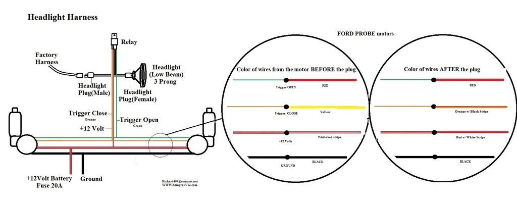
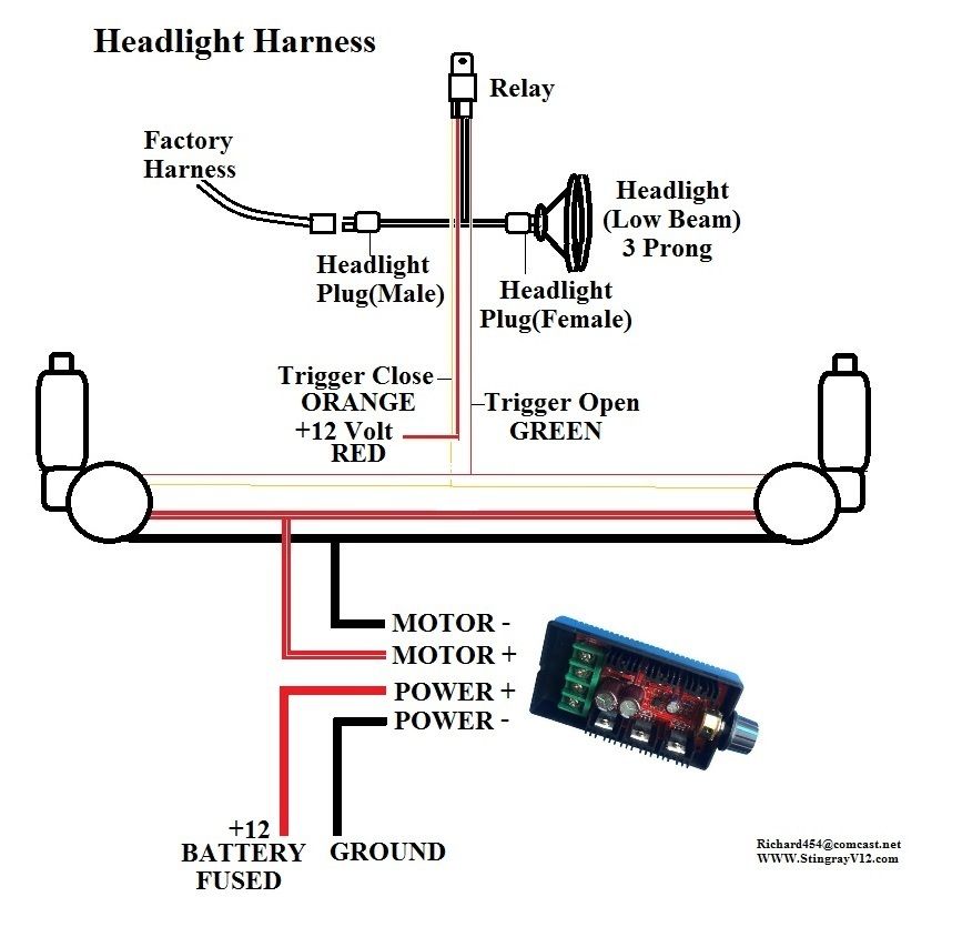
Here's a visual for you-
I've broken it down in two pics for clarification-
Power and ground-
Relay power wire (Red) and power for each motor (white w/ red stripe which turns into red w/ white stripe at the factory plug)- these three wirs go to fuse 20A then a constant 12Volt source AKA battery or the Alt terminal or the horn relay...
Two black wires from the two motors go to a ground-
Trigger wires-
green wire from the relay goes to the red wires (before the plug) and stays solid red after the plug.
orange wire from the relay goes to the yellow wire which turns into orange w/ black stripe after the plug.
Sorry about the color changes at the plug- that was Ford's idea...
And here's a wiring diagram w/ a little more description-
Joined
·
978 Posts
Discussion Starter · #9 ·
Here's a visual for you-
I've broken it down in two pics for clarification-
Power and ground-
Relay power wire (Red) and power for each motor (white w/ red stripe which turns into red w/ white stripe at the factory plug)- these three wirs go to fuse 20A then a constant 12Volt source AKA battery or the Alt terminal or the horn relay...
Two black wires from the two motors go to a ground-

Trigger wires-
green wire from the relay goes to the red wires (before the plug) and stays solid red after the plug.
orange wire from the relay goes to the yellow wire which turns into orange w/ black stripe after the plug.
Sorry about the color changes at the plug- that was Ford's idea...

And here's a wiring diagram w/ a little more description-

That's perfect, thank you!  artyon:
Joined
·
978 Posts
Discussion Starter · #10 ·
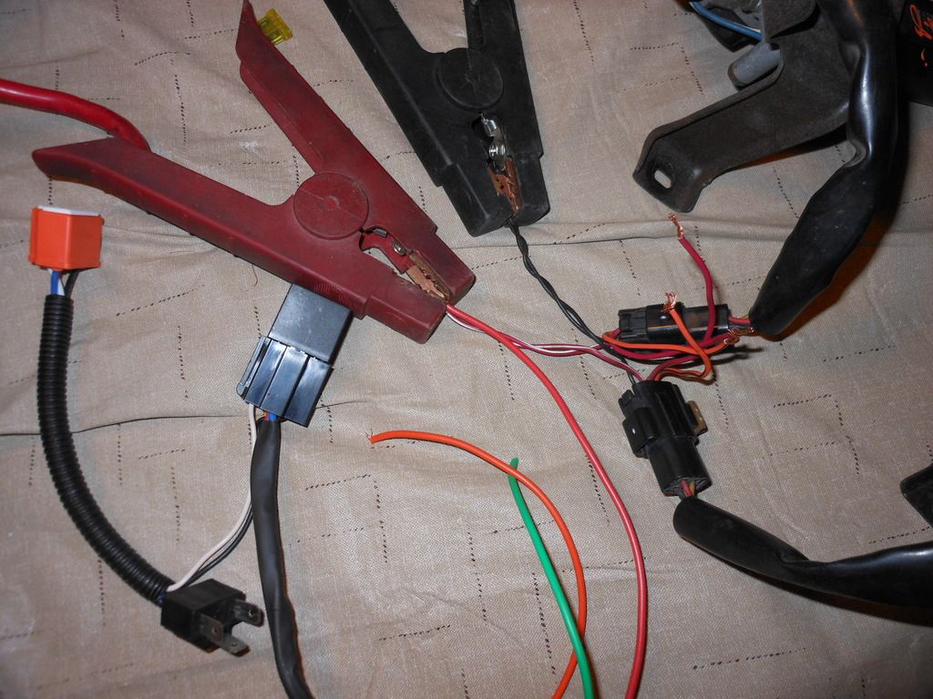
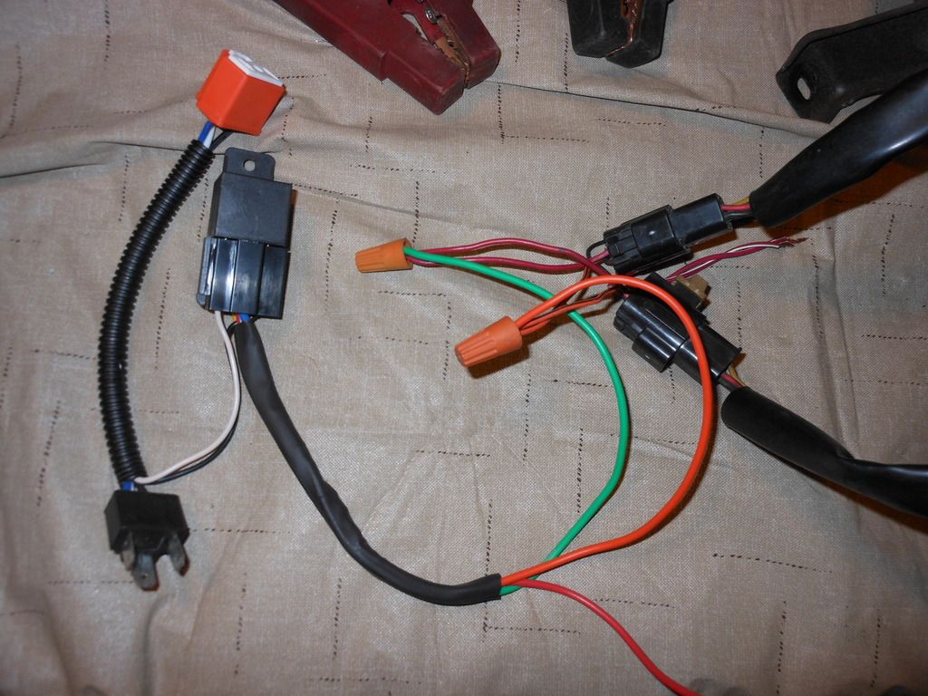
Made up a harness today. I got rid of the factory Ford connectors that were pretty cruddy, and replaced them with singe nice weatherpacks. I soldered everything including the weatherpack prongs, and loomed it all up neat.
I had taken on car measurements so the harness will be a good fit, I plan on doing the 'outside' option for mounting the actuators as I have my cold air intake that drops down in front of the center of my radiator as well as a large auxiliary trans cooler.
The idea is everything will be easily removable if need be to replace an actuator or somethin. I also got some black loom clamps to tuck everything up and out of the way so it'll all look neat.


Joined
·
978 Posts
Discussion Starter · #11 ·
Did a little tear down today. Everything came apart really easy, benefit of the car being a good weather only driver. Just waiting on the headlights and harness from Speed Direct and I'll start putting everything together.
Cool view of my intake with the hood off:

Old hazy sealed beams:


Not sure what the hell that is!


My trim rings were pretty nasty:

So I polished em up while they're off:

Joined
·
978 Posts
Discussion Starter · #12 ·
More progress! I'm still waiting on the bulb conversion from SpeedDirect, so I'm just chipping away at this a little bit at a time.
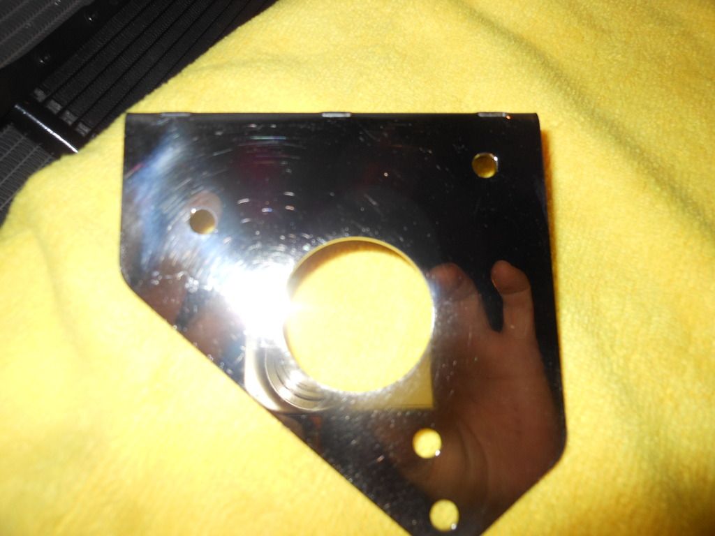
Today I modified the Probe arms to accept the new heim joints, installed the harness I made for the actuators (plus the one I got from Richard454), made a little repair on my passenger side headlight bucket, and installed the actuator brackets (also from Richard). I also painted as I went including the headlight buckets and the Probe actuator arms.
After disassembling my passenger side vacuum actuator I found that the headlight bucket had cracked down the middle where the stock actuator mounted. After talking to Richard, I decided to reinforce the mounting point with some 16ga steel cut out to fit behind. I painted it up and you can't even tell it's there.

Passenger side marked for the clearance cut for the actuator rod. (I went up 1/3" from the top of the stock hole) (Note the crack down the middle of the bucket)

Driver side marked up

Cuts made for clearance


Harness installed

Passenger side bracket installed

Driver side bracket installed

Brackets and Harness

Probe actuator arms, stock balls cut off and drilled out. I drilled it out to 5/16" to match the new heim joints I got from Richard

Heim joints installed on the arms. I used 5/16" bolts, they fit perfectly in the heim joints.

The stuff from SpeedDirect should be here Friday, so I hope to finish this up this weekend. I'll keep updating with pictures, hopefully they'll help someone else down the road artyon:
Joined
·
978 Posts
Discussion Starter · #13 ·
I finished up the conversion today and installed my new headlights from Speed Direct. The Speed Direct kit is great, the harness for the new lights is top notch. I'll have to get a picture of it.
The Probe conversion went off without a hitch. The passenger side is slightly slower than the driver's side, and they're both slower than all the other videos I've seen. They're not vacuum slow by any means, they just operate nice and smooth. Richard, is there a way to adjust the speed if I decide to though? Would adjusting the tension in the actuator shafts do it?
As far as the headlight conversion, that went well. However, I had to hack up my buckets and cups a LOT more than Speed Direct made it sound like. My car is custom enough that I don't really care, plus it's all out of sight. My only concern is that cutting so much out might compromise the strength of the bucket and cause flex, but it seems ok?
The only other issue I'm having is the sockets keep wiggling themselves loose when the headlights go up and down, but it's only for the hi-beams. I'll have to mess with them some more.
Heres the driver's side all cut up.

Passenger side actuator mounted and hooked up. You can also see part of the Speed Direct harness.

Here's another shot of the Headlight harness

And......

I've got to thank Richard454 for fielding all my questions, he was a big help!
Joined
·
1,323 Posts
Richard, is there a way to adjust the speed if I decide to though? Would adjusting the tension in the actuator shafts do it?
I've got to thank Richard454 for fielding all my questions, he was a big help!
You are welcome Kevin!!!
Nice write up!
As far as the speed- here's a couple ways to do it-
You can simple wire the motors in a series- this will operate at ½ speed-
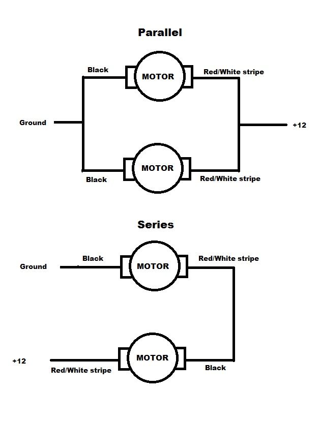
Or you can use a PWM- pulse width modulator- on eBay for $20 -and have complete control of the speed
http://www.ebay.com/itm/DC-Motor-Sp...991824?hash=item2ec9508090:g:NSIAAOSw0HVWDaD6

How to wire-
I used a PWM to control the speed of my License plate/reverse lights

Joined
·
761 Posts
They seem to be operating at a decent speed. I wouldn't make them any faster/slower. :thumbsup:
Great job on the conversion!
:cheers: Les
Posted by: thedecors03.blogspot.com
Source: https://www.digitalcorvettes.com/threads/ford-probe-headlight-conversion.263345/